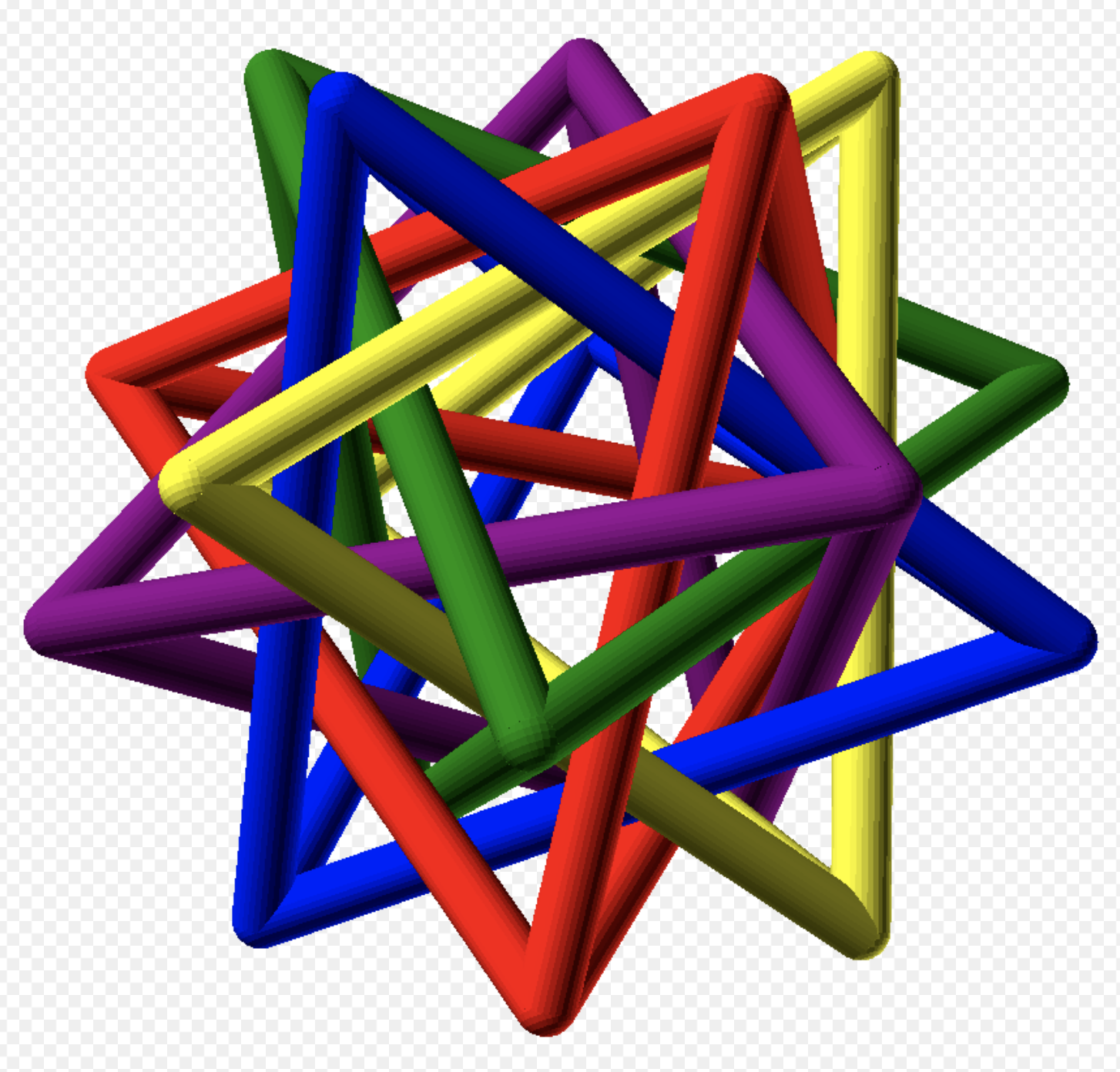
Well, it has been long enough that I would like to reinitiate the Intersecting Tetrahedrons project. I have sufficiently recovered from the disappointment of the last effort to begin fresh. Hopefully, many of the learnings from the second attempt will enable this third attempt to deliver the wooden stellated icosahedron. The "too big to fit" problem arose because the angle of the bar's triangular cross section changed from 30° to 35.25°. This resulted in a base width of 1". This iteration will have bars that are 10" X 5/8". With a top included angle of 70.5° the bottom of the triangle will then be 0.870" (or 7/8"), which was the original base width when the included angle was 60°. The ratio of triangle height to bar length is 14.8, significantly larger than the recommended 12. But I don't think the ratio is so big that the tetrahedra will move around excessively. "Project Origami" has a good description of optimizing the length vs. width of the bars as well as a set of diagrams for assembling the final model.
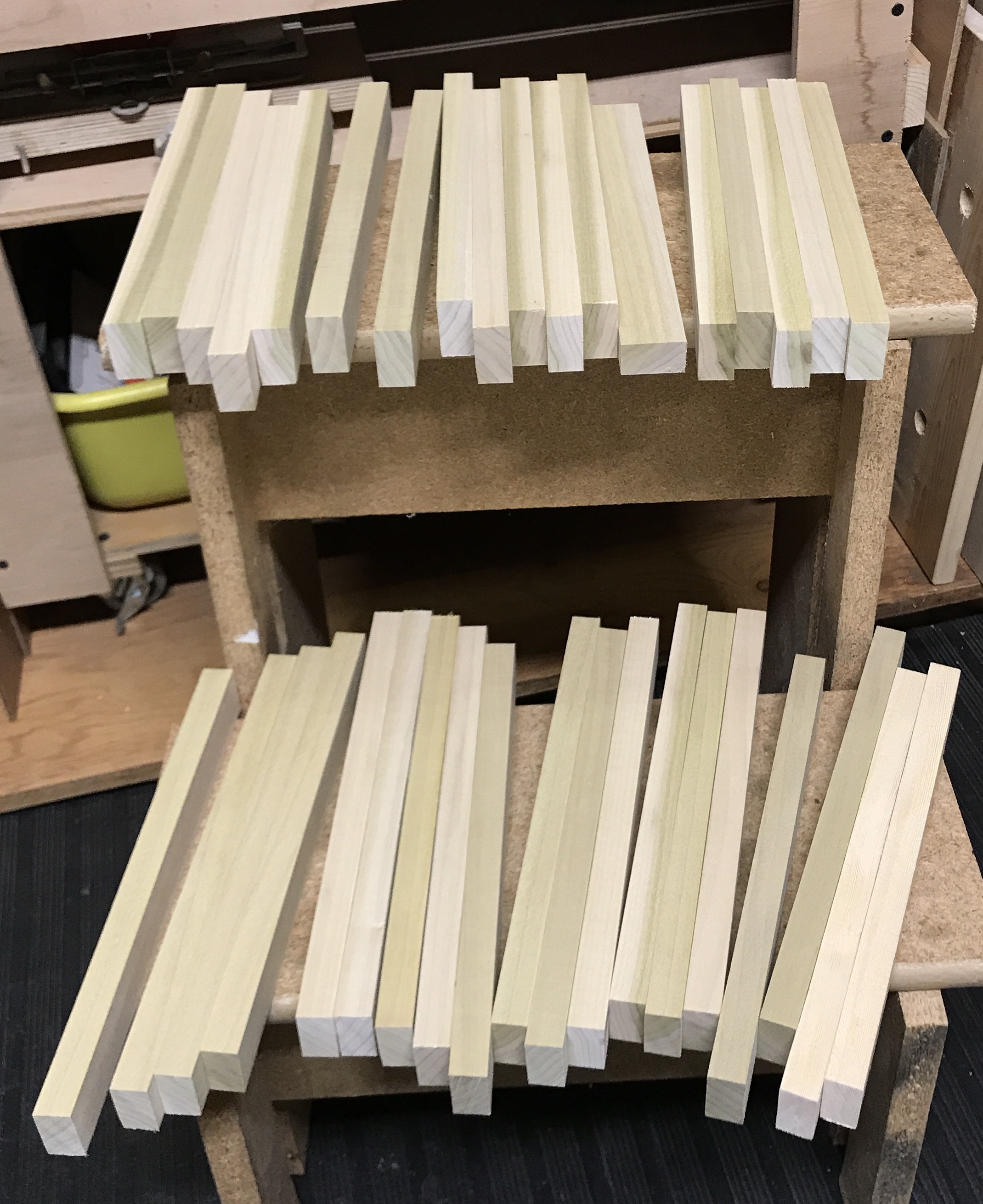
I plan to make the legs from 1" X 2" stock. Poplar is the least expensive step up from pine and should be pretty clean wood. Of course the milled size is 3/4" X 1 1/2". Four 8' lengths should provide thirty-six 10" blanks. I will cut the boards to the requisite 10" length prior to ripping to the desired 5/8" X 7/8" size. The 8' lengths were cut by hand at 53" to give a second piece 43" long. These lengths were cut to 10 1/8" using a table stop and the cross cut sled. After cutting these 10" lengths and a few extra a stop was clamped to the cross cut sled and the parts were accurately cut to 10.0". They were then ripped to 5/8" X 1 1/8" with the rip fence and a featherboard. The 37 blanks are shown below.
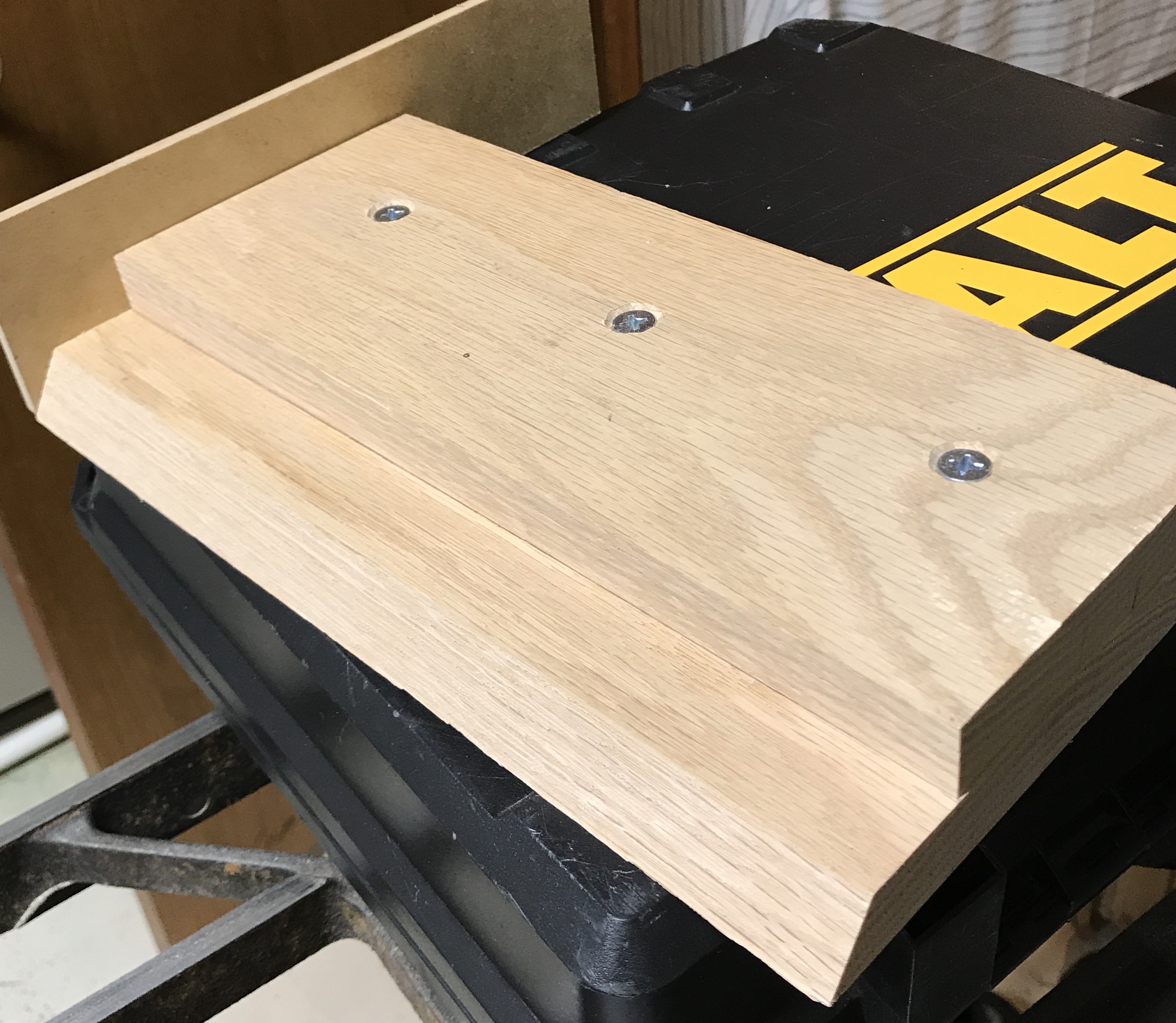
So far I have not been able to find the jig used in Tetrahedron Redux for cutting the triangular cross section. Therefore a new jig is planned. The jig was cut from a 3/4" scrap of oak. It was about 12" long and was cut into two pieces about 8" and 6" wide. The blade was carefully angled to 35.25° off of vertical and both parts were cut on the long side. The smaller part was drilled for three holes to fit 1/4" bolts. The top was place in the first cut position (i.e. a vertical side was 1 1/16" from the angled edge of the bottom and clamped. The holes were transfered making sure the top was parallel with the bottom. The holes in the top part were countersunk pretty deep. 1/4" holes were drilled in the bottom and the bottom part was countersunk on the bottom side with a 3/4" Forstner bit about halfway through the board. The parts were joined with bolts, washers and nuts. Separate holes need to be drilled for the second cut, but I would like to set the appropriate distance when a suitably cut part is in hand. A 1/4" X 3" X 8" piece of scrap was attached to the end of the bottom with three screws to serve as a stop. The jig is shown below.
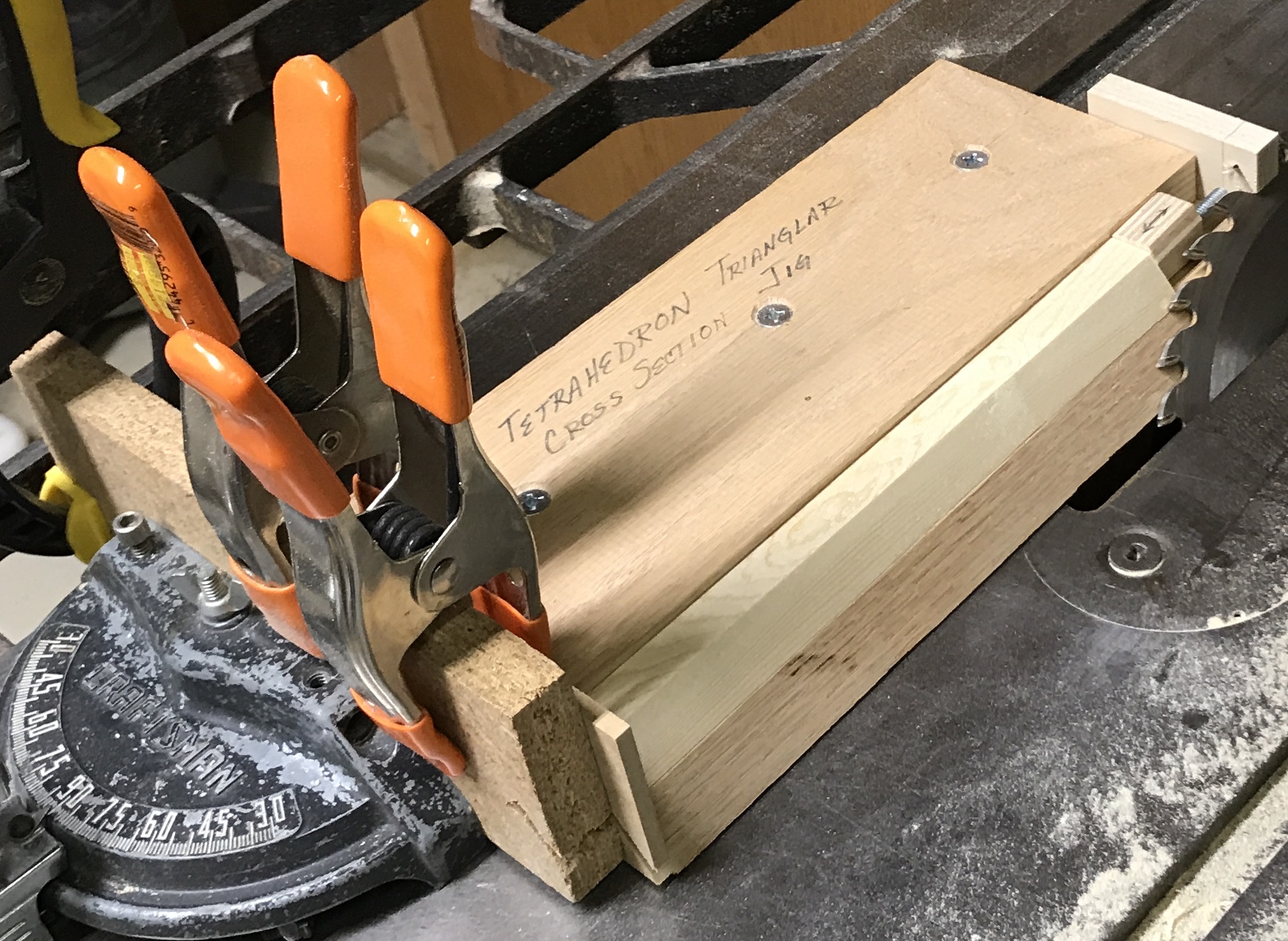
When getting ready to use the jig, I realized it was missing any clamping ability. This was remedied by adding an end plate at the far end with a screw through it. A 1/2" X 2" X 3" scrap was drilled and tapped 1/4-20. Two through holes for attachment screws were also drilled and countersunk. The screw holes were transfered, the end plate was screwed in place and a 2" bolt and lock nut were threaded into position. The jig was a little long so a small block was used as the clamp on the part to be cut. The two pictures below show the jig as used. To use, the jig is clamped to the miter fence such that the blade just barely rotates freely. The jig needs to be held tight to the table before clamping it to the miter gauge. The part to be cut is inserted and secured with the screw, clamping block and lock nut.
Cut all of the parts on this first setting establishing the first angle of the triangular cross section. Now to determine the new setting for the second cut. The position of the top slide was approximated and then the holes were transfered from the bottom to the top. The holes were drilled 1/4" and then slots were cut on the mill and the slots were chamfered. Now the top can be adjusted so I can sneak up on the second cut. After careful measurement of 7/8" across the length of the jig, the first cut was made. The width of the base of the triangle is closer to 3/4" than 7/8", but the top is just cutting to the line of the previous cut. I don't understand the reason for the difference in size, but have decided to go with it. After cutting about a dozen bars the bar started to rattle slightly when beginning the cut. On the first cut this meant the bar was not held tightly enough and a twist on the screw clamp fixed the problem. This time further tightening the screw clamp did not help. It may be because the block between screw and part is smaller. To add further clamping support some sandpaper was in order. A small scrap of sandpaper was epoxied to the end of the clamp block and trimmed to fit.
Epoxy was used because the 3M spray adhesive would no longer spray, even through an unused nozzle. The can was clearly full of adhesive.
The sandpaper was effective even though the epoxy had not completely dried. After a few cuts it was necessary to use a wrench to tighten the screw and the lock nut as my hands got sore. All of the bars were cut to the required triangular cross section. The jig in the second cut configuration and the 37 cut bars are shown below.
The jig used for cutting the ends of the bars was found and then used to cut the ends. The blade was set at a 45° angle as was the miter gauge. The phone was again used to set the blade angle and the framing square was used to set the miter angle. The blade was amazingly well aligned with the previous cut! The jig was clamped to the miter gauge with two bar clamps. It was adjusted so the blade just touched the end. A bar was clamped in and cut just going past the tip. A number of bars were cut on both ends. One of the bar clamps loosened over time. I could see that some of the bars were now about 1/16" shorter than before. The clamp was retightened and cutting proceeded. Now the bars are slightly longer than the first batch. Most of this should get cleaned up in the second pass. We shall see! The jig as set up for a cut is shown below.
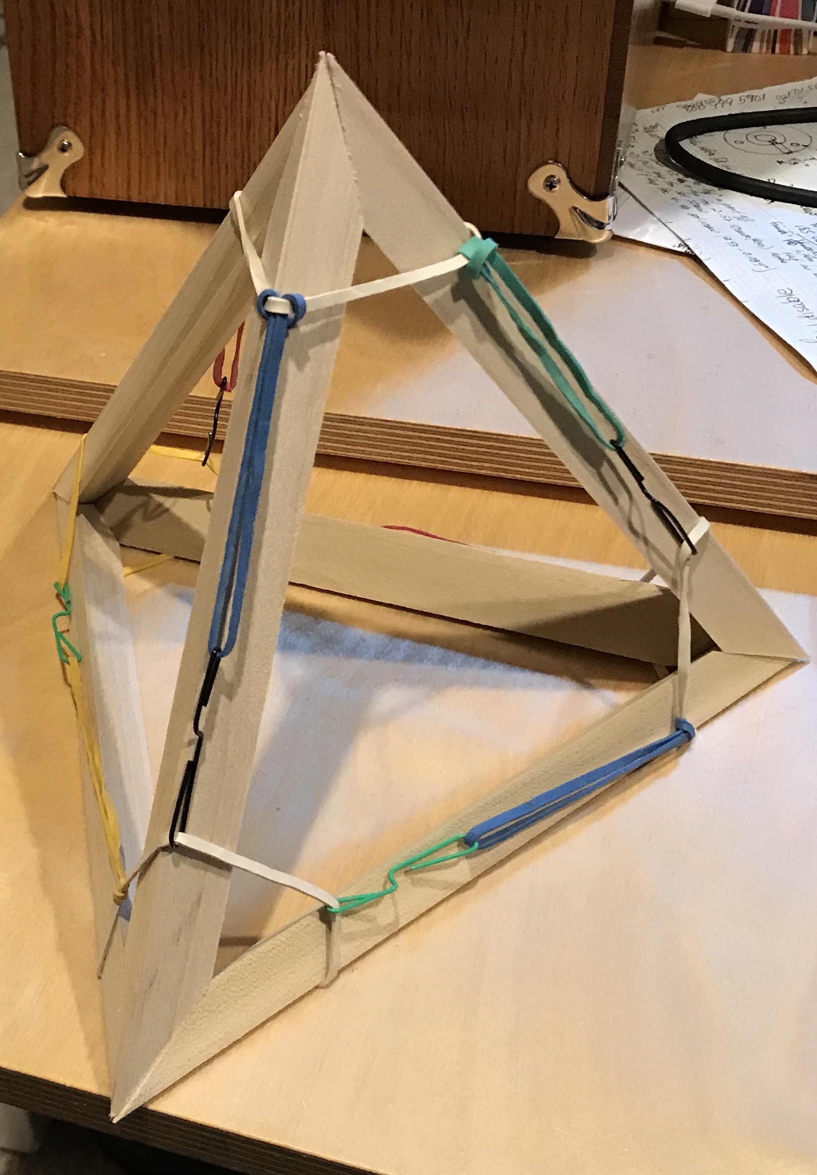
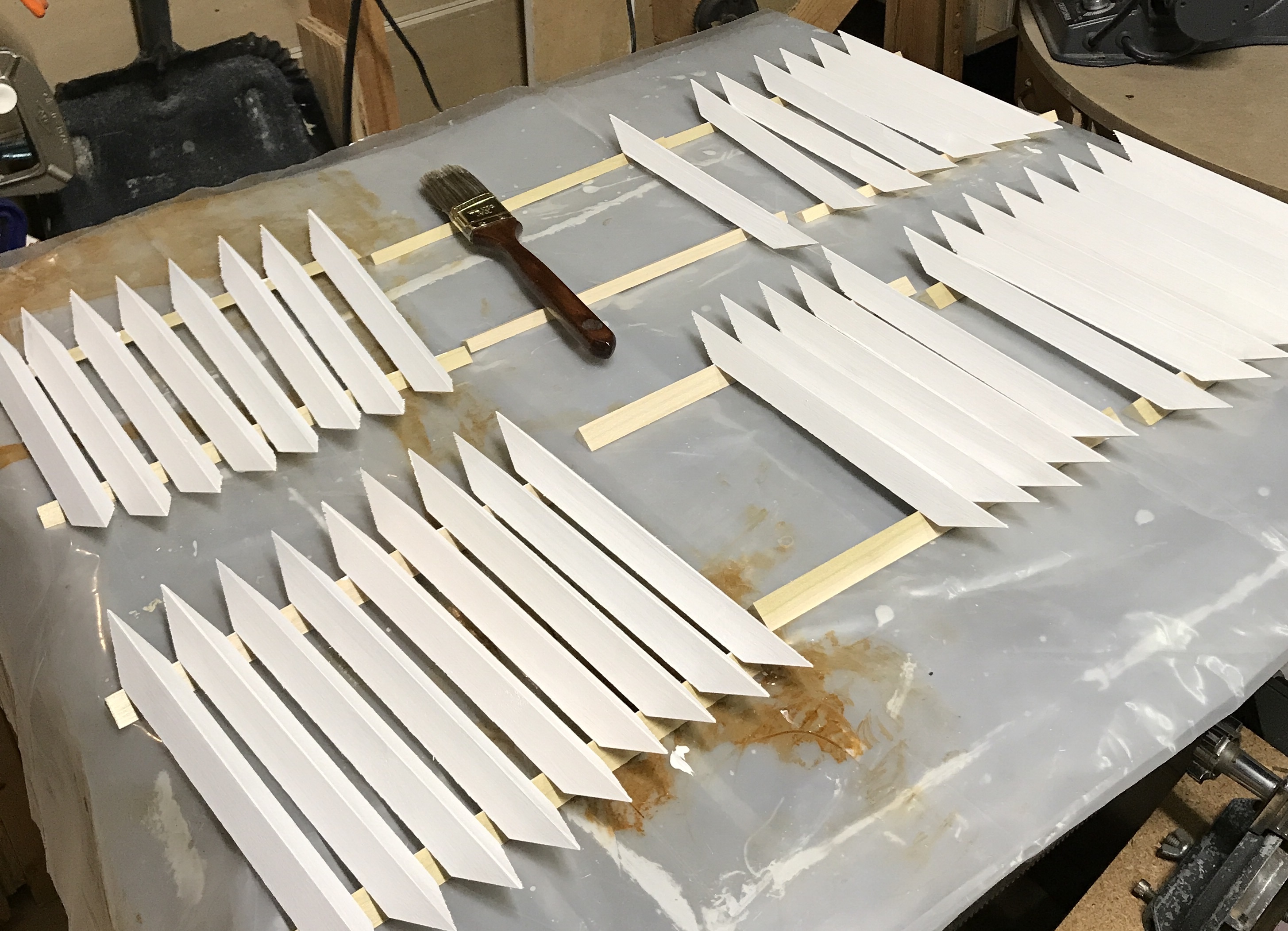
After cutting the first angle on the ends the miter gauge was reset for -45° via the same framer's square procedure described above. The second angle was cut on all of the the ends. This time the clamps were periodically checked for tightness. The bars were aligned slightly proud (1/64") at the cutting end. This gave symmetrical cuts. The seven shortest bars were used for a test fit with the rubber band/paper clip clamping system. This is shown in the following picture. The rubber bands are not very tight. The paper clips probably need to be folded in half to provide adequate tension. A little sanding, followed by priming and painting will pave the way for glue-up. I decided to prime the bars prior to sanding. They were quite smooth from the table saw and they will need sanding after the primer. The second picture below shows the "vampire stakes" primed with Killz (sic) (the version with silver nanoparticles).
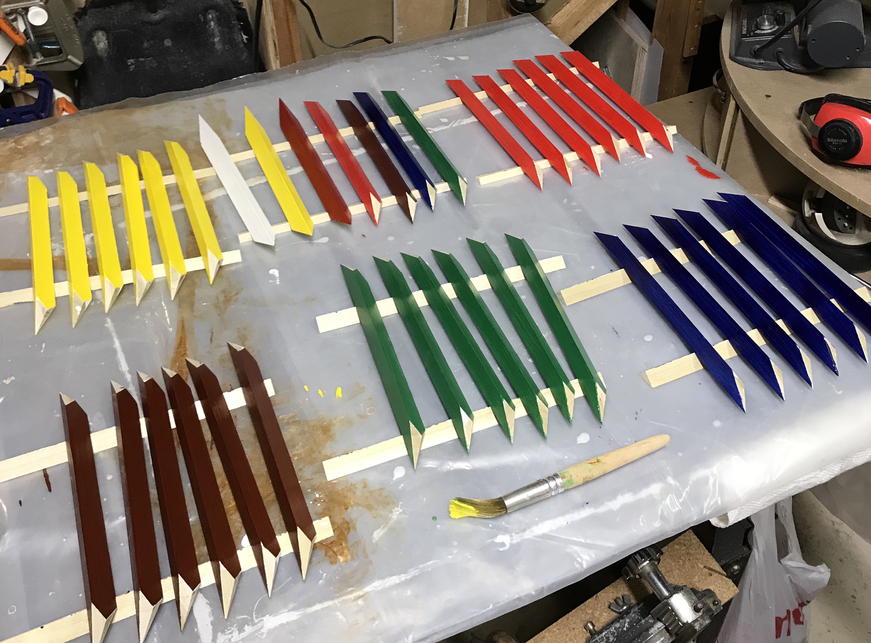
The bars were painted today. The two smaller sides were painted and after about 2 hours the larger side was painted. All of the paint dried quickly. The picture below shows the chosen colors. This is the same acrylic paint used before, though the color choices are not identical. An extra bar was painted in each color. These may serve as backups or they may be made into a free-standing tetrahedron just for the heck of it.
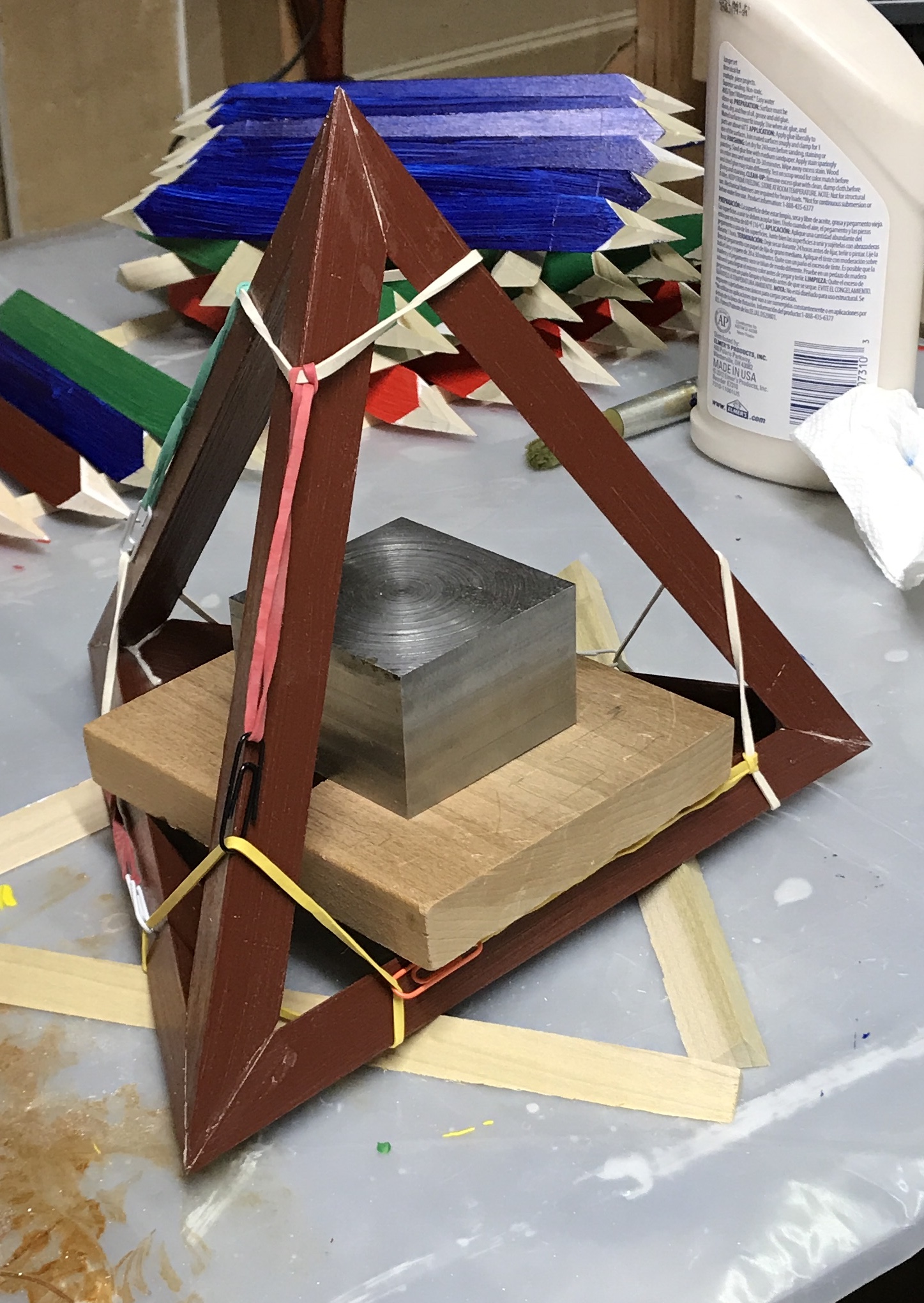
The first tetrahedron was glued up this morning. Decided to use wood glue. Experimented a bit yesterday and the setup time seemed long enough, about 5+ minutes. I adjusted the paper clips on the rubber bands, but the harness still seems a little loose. I again used a weight to hold the glued bottom three bars and then added the top bars individually. The first results can be seen in the picture below. A very nice fit and easily clamped first tetrahedron. Gluing the interpenetrating tetrahedra gets ever more challenging from here on.
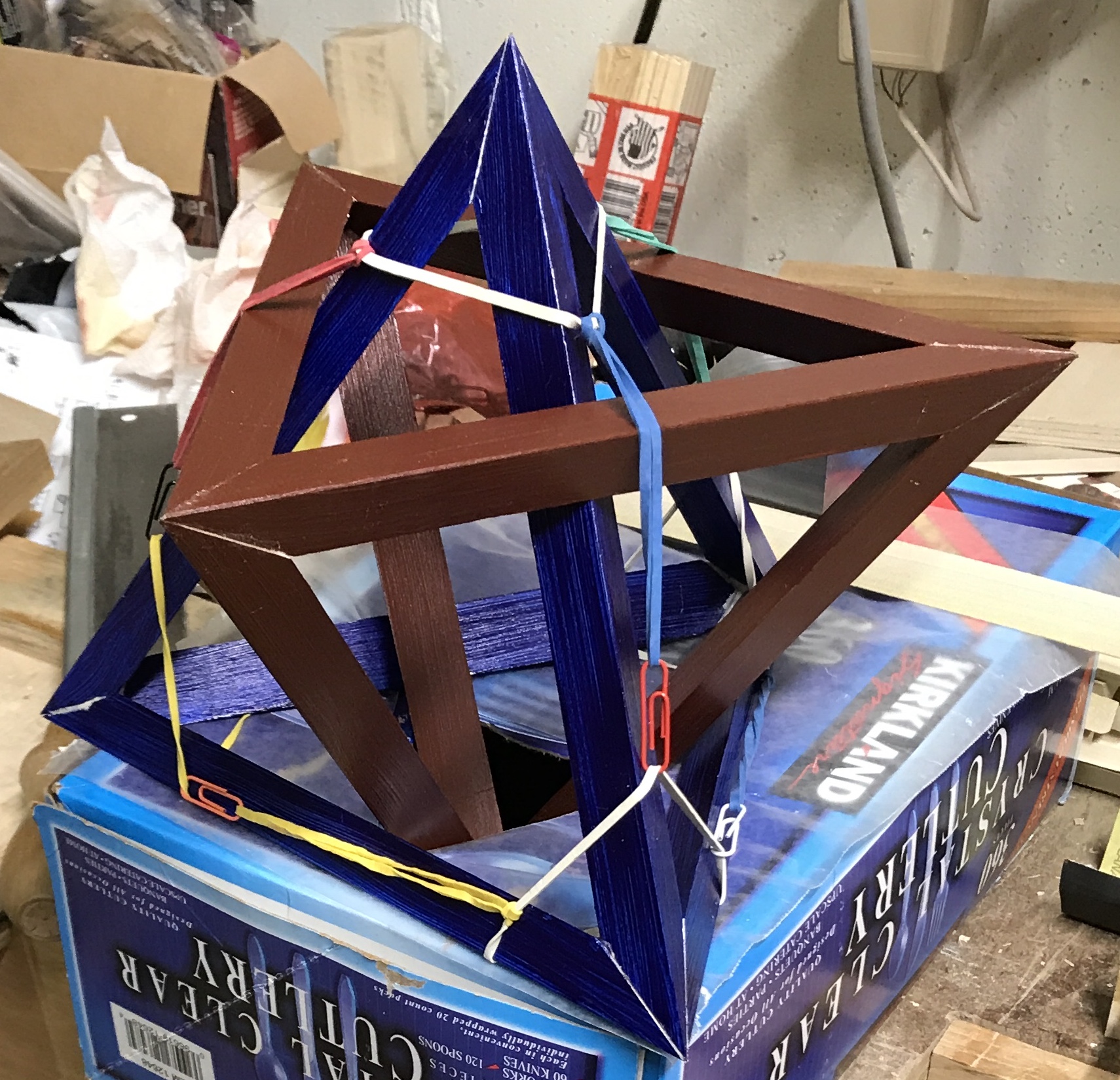
A triangular hole was cut into a box where a point of the glued tetrahedron will sit. The points of the triangular hole approximately corresponded to the midpoints of the bars. Wax paper with a similar hole cut into it was placed over the box with holes aligned. The rubber band harness was put in place such that all vertices of the glued tetrahedron went through holes in the sides of the harness with all of the bands outside the tetrahedron. It was aligned to capture each of the four vertices of the new tetrahedron. The glued tetrahedron was placed into the hole point down. Three blue bars were laid around the hole. The ends of the three horizontal bars were pushed through the corresponding rubber bands and covered with glue. An end of each of the three remaining bars was glued, inserted through the top rubber band of the harness, inserted through a bottom rubber band capturing its vertex, and aligned with a bottom vertex. The top ends of these vertical bars were covered with glue. The top vertex was aligned as were the bottom three vertices. It all came together with minimal fiddling. The picture below shows the pair of tetrahedra just after gluing.
In order to thread in the bars for the third tetrahedron the first two were held together with two rubber bands. This kept these first two reasonably stable. The two glued tetrahedra were supported on blocks in an orientation similar to that shown in the above reference. The green bars were then threaded through the pair of tetrahedra and held loosely in place with a rubber band for each bar. The harness was put around the whole and the unglued bars were put through the appropriate rubber bands. Then the support rubber bands for the new bars and the bands holding the two glued tetrahedra were removed. With a lot of adjusting the bars could be arranged into a pretty good tetrahedron. The challenge is a couple of bars on the bottom provide some support and consequently want to rotate out of the correct orientation. I will need to think about how to better manage the orientation of the bars prior to gluing. But at least they fit!!!
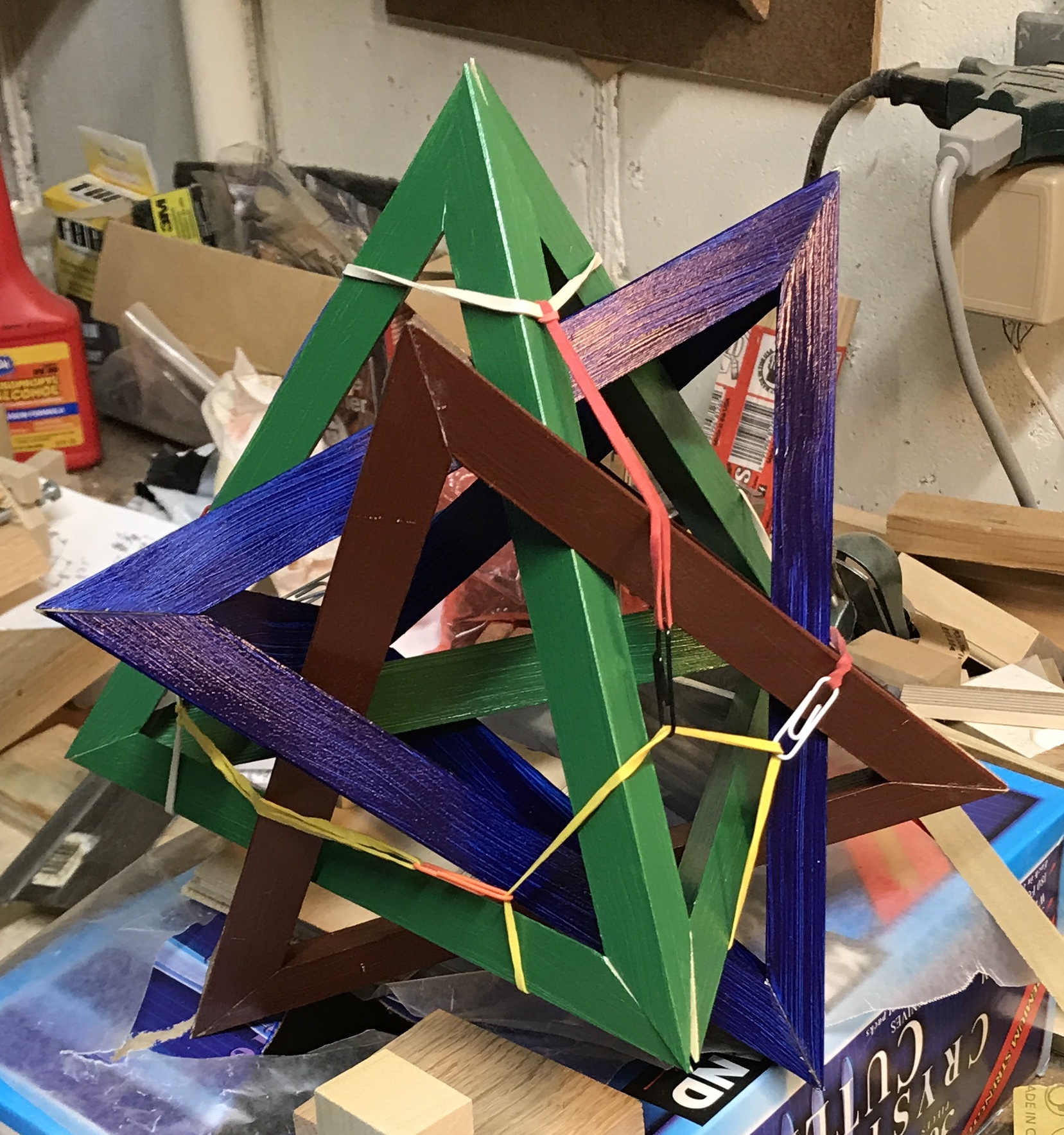
Glued up!! That was a pain in the derrière! I just went for it. Glue was applied to all of the ends and then each vertex was adjusted repetitively to align the bars. After some cursing it eventually went together and after more fiddling/cursing I was satisfied with the four joints. The drying glue actually helped to stabilize one joint while working with another. I am not satisfied with the support that I have for the two completed tetrahedra.
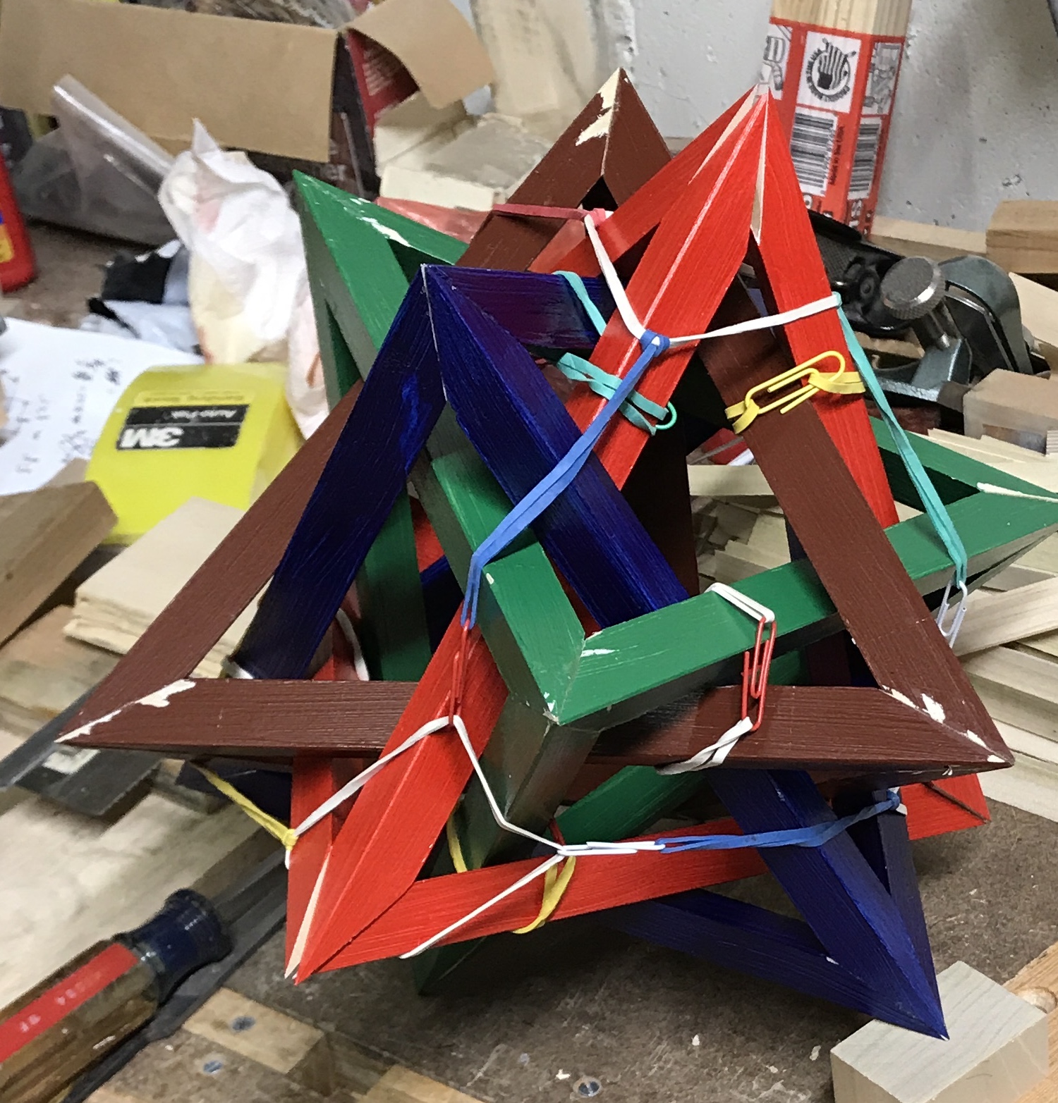
I had it and then I lost it!!. What was going through my head four years ago when I got on this rollercoaster? The three tetrahedra were planed a bit on the vertices to remove glue. (Touch up will come last.) I arranged the three tetrahedra as shown in the picture and carefully inserted three bars for the the fourth. They fit nicely. I then removed the three bars in order to put in rubber bands for support. Enough movement of the three tetrahedra ensued to mess up the alignment. I spent the next hour trying to recreate the right arrangement with no success. So I slept on it. This morning I was able to recreate the picture in the pdf and insert all of the bars for the fourth tetrahedron. The picture below shows the fourth tetrahedron with harness in place just prior to glue-up. Gluing this one was not quite as successful as the first three. The alignment is not quite as good for some reason, but it is good enough. After letting it dry the vertices were "trued" up a bit with the chisel.
The vertices that had been scraped, sanded, or chiseled were primed. This included all but a couple of the blue, second tetrahedron, vertices. The paint was left to dry overnight. The final bars were put in this morning. I wasn't sure this was going to be possible as the fit seemed to be getting tighter with each new tetrahedron. Once I was able to orient the four tetrahedra with the picture in the reference, the bar placement was obvious and they pretty much slid right into place. The ends did not all meet perfectly, but with glue and 5 minute finger clamping the vertices are all respectable. While the glue was drying on the yellow tetrahedron the primed red vertices were painted. The stellated icosahedron was suspended from the stored vise and the remaining primed vertices were painted. Only the yellow vertices remain to be cleaned up, primed and painted. The picture below shows the almost finished product. Notice the characteristic pentagon in the center.
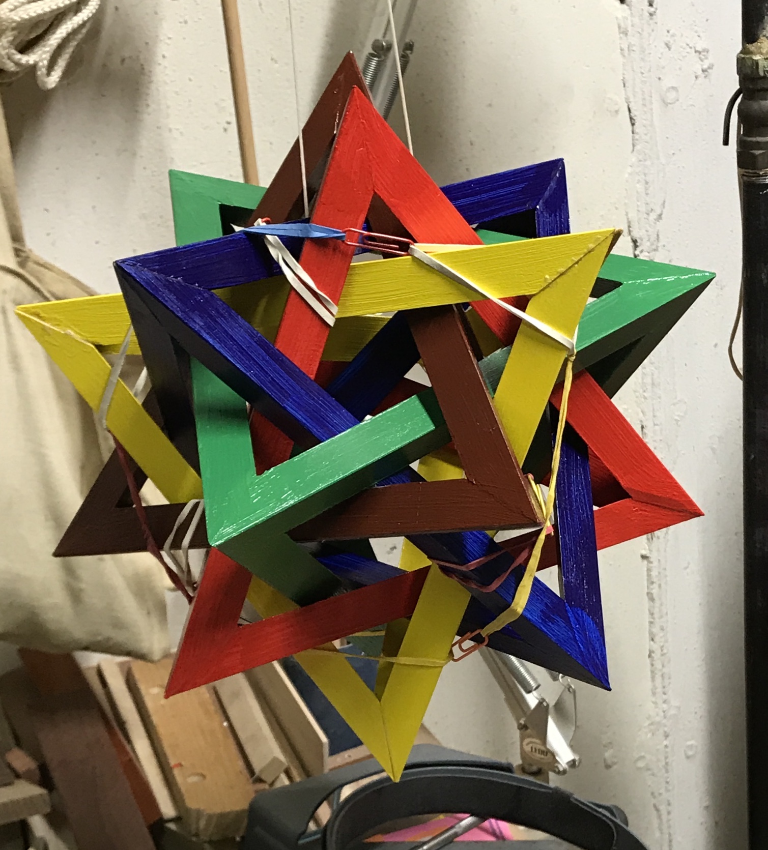
The rubber band harness and the rubber bands used for holding the pre-glued bars in place were removed. The yellow vertices were cleaned up with a chisel. Some vertices needed significant work to get an acceptably smooth transition to a point. These final four vertices were then primed and left to dry for a few hours. Meanwhile the remaining six painted bars, one of each color, were glued up into a tetrahedron. The fit was better than expected, given that three different length bars were used. Four primed yellow vertices were painted this morning with the medium yellow acrylic paint. The five intersecting tetrahedra are complete! The photos and video below show it in all of its glory.
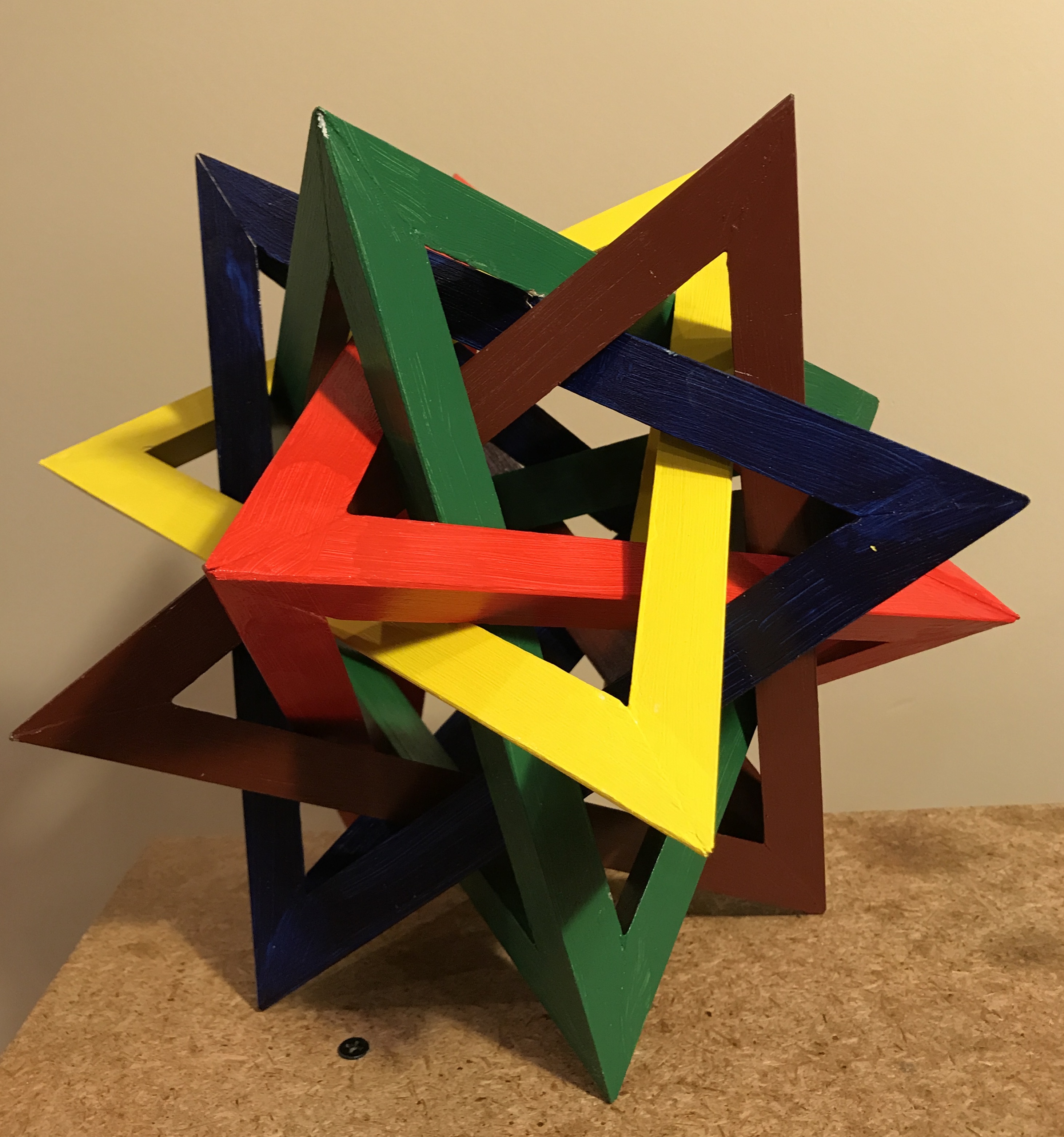
The fit as mentioned got tighter and tighter with each additional tetrahedron. The final product has no free play at all. The ratio of bar height (5/8") to bar length (10 3/4") is 17.2 and could not have been a single iota smaller! I do not know why a ratio this much larger than the reference recommends (12-14) was required. I can only guess it is due to the different angles of the triangular cross section. A little luck made up for my mediocre planning!